






Cable Tray Connectors may look like small fittings, but they help determine whether a route stays aligned, secure, and serviceable. A straight splice joins two tray sections; horizontal and vertical fittings guide changes in direction; reducers connect different widths; and hold-down or bonding connectors address support and electrical continuity. The right choice depends on tray material, loading, environment, and installation details. Small parts matter.
The International Energy Agency’s Electricity Grids and Secure Energy Transitions report says annual grid investment needs to rise above USD 600 billion by 2030. That figure describes grid infrastructure broadly, not the cable tray connector market. Still, it signals why dependable cable-routing systems deserve careful specification. IEA Executive Director Fatih Birol has said, “There is no energy transition without transmission.” His observation concerns energy networks, not connector design, but it underscores the importance of reliable infrastructure.
This guide compares common Cable Tray Connector types and their practical uses, from splice plates to expansion and bonding connectors. NEMA VE 2 installation guidance also reminds designers and installers to follow system-specific requirements and manufacturer instructions. A connector that fits on paper may not suit the site. Check alignment, fastener access, corrosion exposure, and movement before installation. Details can be missed. A named, connector-specific expert quotation should be verified against a primary source; inventing one would weaken an otherwise useful introduction.
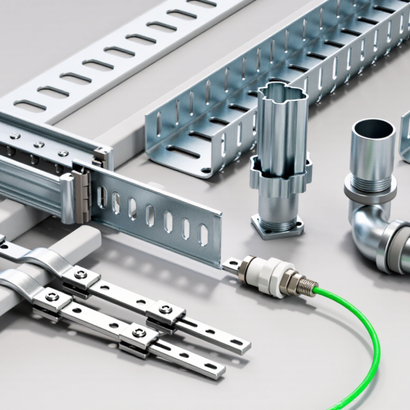
Straight splice plates are among the most common cable tray connectors. They join two straight tray sections end to end, keeping the side rails aligned across the seam. A typical plate sits against the tray’s side rail and is secured with bolts through matching holes. The exact plate shape and bolt pattern depend on the tray type and dimensions. Check compatibility before installation; a plate that nearly fits is not a reliable fit. Even a small gap can make alignment harder.
Tips: Bring the tray ends together on a stable support. Check that the rails sit flush, then install the specified bolts and tighten them to the project requirements. Do not guess. Over-tightening can distort thin metal; loose hardware may let the joint shift.
In practice, this connection is easy to rush when several sections are being installed in sequence. Pause to check alignment from above and along the side before moving on. A straight splice plate is intended for joining sections, not replacing the supports required by the tray design. Also, do not assume every bolted joint provides electrical continuity. Where bonding is required, use the specified method and verify the connection. Small details matter.

Rigid splice connectors join two straight tray sections and hold their alignment. They suit runs where the tray does not need to change direction or absorb movement. Match the connector to the tray’s width, material, and side-rail profile. Tighten fasteners to the specified torque; a joint that looks snug may still loosen under load.
Adjustable connectors allow installers to form horizontal or vertical angles, or accommodate small changes in direction. They are useful around columns, ducts, and other obstructions. Check the bend before tightening, since even a slight mismatch can twist the tray or make a cover sit unevenly. Small details matter. Adjustable hardware is not a substitute for a properly planned bend.
Expansion splice connectors let tray sections move as temperatures change, particularly on long runs or near building expansion joints. Set the gap according to the project details and installation temperature, rather than closing the joint by eye. The connection may also need a bonding jumper to maintain electrical continuity; follow the design and applicable requirements. One detail is easy to overlook: a neat-looking splice is not necessarily a correctly aligned or electrically sound one.
Expansion connectors let a cable tray run move without forcing joints, supports, or fittings out of alignment. NEMA VE 2, Cable Tray Installation Guidelines, advises accounting for tray material, run length, and the expected temperature range when locating expansion splice plates and setting their gaps. The gap should reflect the tray’s temperature during installation, not an assumed “average” day. Small detail. But it matters.
ASHRAE Handbook—Fundamentals lists approximate linear expansion coefficients of 12 micrometres per metre per °C for steel and 23 for aluminum. Across a 30-metre run and a 50°C temperature swing, that suggests about 18 mm of steel movement or 35 mm of aluminum movement. These are estimates, not installation dimensions; confirm actual material data and use the applicable NEMA VE 2 guidance. For example, a sunlit roof run may heat far beyond the morning air temperature. Set the connector gap accordingly, and arrange supports and fixed points so the tray can slide as intended. A calculation can look precise while missing local heating, restraint, or an unexpected temperature range. Check the site conditions before relying on it.
| Connector type | Primary purpose | Movement accommodated | Typical application | Installation considerations |
|---|---|---|---|---|
| Straight splice connector | Joins two tray sections in a continuous straight run. | Normally provides a fixed connection; it is not intended to serve as a thermal expansion joint. | Routine straight runs where significant relative movement is not required at the joint. | Use the connector type and fasteners specified for the tray system. Do not substitute a standard splice for an expansion connection where thermal movement is expected. |
| Expansion splice connector | Joins tray sections while allowing controlled longitudinal movement. | Allows the tray ends to move relative to one another as temperature changes. | Long runs, outdoor installations, and locations subject to substantial temperature variation. | Determine joint locations and the installation gap from the applicable NEMA VE 2 guidance and the tray system manufacturer’s instructions. Set the gap for the expected temperature range and the temperature at installation. |
| Flexible connector | Connects tray sections where limited flexing or relative movement is needed. | Accommodates flexing or movement within the connector’s intended limits; it is not automatically a substitute for a designed expansion joint. | Transitions or locations where vibration, alignment variation, or localized movement is a design consideration. | Confirm the connector’s permitted movement, load capacity, bonding requirements, and suitability for the specific tray material and installation. |
| Horizontal adjustable splice connector | Connects sections through a horizontal direction change or alignment adjustment. | Provides adjustment for routing and fit-up; it is not generally designed to accommodate long-run thermal expansion. | Horizontal bends or field-adjusted tray routes. | Check that the completed joint maintains the required mechanical support and electrical continuity for the installation. |
| Vertical adjustable splice connector | Connects sections through a vertical direction change or elevation adjustment. | Provides adjustment for elevation and routing; it is not generally an expansion joint. | Vertical bends, risers, or changes in tray elevation. | Follow the tray system’s installation instructions and support requirements at the change in direction. |
| Bonding or grounding jumper | Provides electrical bonding across a joint where required by the design or applicable electrical rules. | Can preserve electrical continuity while allowing movement when a suitable flexible jumper is used. | Expansion joints or other joints where electrical continuity must be maintained. | Use a jumper suitable for the expected movement and environmental conditions. A jumper does not replace the mechanical expansion connector. |
Cable tray fitting connectors join straight sections to elbows, tees, crosses, and reducers. They help keep the route aligned as it changes direction or branches. At an elbow, connector plates attach the curved fitting to straight tray sections. A tee creates a branch, while a cross connects four paths. Reducers transition between tray widths, so the connector pattern must match both ends. Small details matter.
Choose connectors that suit the tray material, width, and load requirements. For example, a wide tray carrying bundled cables may need the specified number of splice plates and fasteners at each joint. Align the rung spacing and side rails before tightening; a small offset can make later cable placement awkward. Check that cut edges are smooth and that the joint does not obstruct cable entry. The exact hardware varies by tray system, so follow its installation guidance rather than assuming every fitting uses the same plates. I have seen neat-looking joints loosen after repeated adjustment. That is a reminder to inspect the connection after installation, not just during assembly.
Bonding jumpers keep a cable tray electrically continuous when joints loosen, coatings interrupt contact, or expansion sections move. NEC Article 392.60 requires metallic tray systems to be grounded and bonded under Article 250. If the tray serves as an equipment grounding conductor, Table 392.60(A) sets minimum side-rail cross-sectional areas by tray material. It is a measurable requirement, not a visual judgment. Looks connected. May not be.
At expansion joints and other points where continuity is interrupted, install bonding jumpers when the tray is used as the equipment grounding conductor. Size and install them under the applicable Article 250 rules, and use flexible connections that accommodate tray movement without strain. NEMA VE 2 installation guidance also highlights splice and expansion assemblies as locations where continuity needs attention. A quick visual check helps, but it cannot confirm a low-resistance path. Verify connections during installation and after changes; paint, corrosion, and loose hardware can undermine an otherwise sound assembly. Check the NEC edition adopted by the local authority, since requirements and numbering may change. I have seen tidy-looking joints fail a closer inspection. That detail is easy to miss.

