






A 12 Port Fiber Termination Box is a compact enclosure for organizing, protecting, and terminating optical fiber connections. It usually provides space for up to twelve adapter ports, depending on the model and configuration. Inside, fiber cables are routed through splice trays, holders, or protective sleeves. The box keeps delicate fibers away from dust, sharp bends, and accidental pulling.
In practical installations, technicians often mount this box on a wall, rack panel, or communication cabinet. A clear labeling system helps identify each fiber quickly. Proper bend-radius control is equally important. Even a small, careless bend can increase signal loss or damage the fiber. Experienced installers also check connector type, port density, cable entry size, and grounding requirements before installation.
Small box. Serious details.
This article explains what a 12 Port Fiber Termination Box does, how its internal parts work, and where it fits in a structured fiber network. It also examines common materials, mounting methods, protection levels, and maintenance practices. Product specifications can vary between manufacturers, so one general description cannot replace the datasheet. That limitation matters. A box may appear suitable, yet lack enough space for splice protection or future expansion. Reliable selection requires checking real cable dimensions, adapter compatibility, installation conditions, and applicable industry requirements. With those details understood, the enclosure becomes more than a simple container. It supports cleaner connections, safer handling, and more dependable network performance.
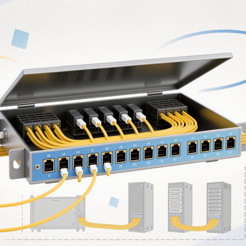
What Is a 12 Port Fiber Termination Box?
What a 12-Port Fiber Termination Box Is and Where It Fits
A 12-port fiber termination box is a small enclosure for organizing and protecting fiber connections. It normally holds up to twelve adapter ports, splice points, or pigtails. Inside, fibers are routed through a tray, labeled, and protected from sharp bends. The box creates a controlled transition between an outdoor cable and indoor patch cords.
It fits between the main fiber cable and the equipment or distribution panel. Installers commonly place it near a building entrance, telecommunications room, cabinet, or wall outlet. In a small office, twelve ports may serve several rooms without requiring a large rack enclosure. In a larger network, it can act as a local termination point before fibers continue to another cabinet.
Installation quality matters more than the box size. Technicians should check cable entry space, bend-radius limits, grounding needs, and the enclosure’s environmental rating. Clear labels make later testing much easier. A loose splice tray can create trouble. So can excessive slack.
During site inspections, installers often find that the planned port count is too exact. Future connections may need spare capacity, even when the current design uses only eight ports. A 12-port box is practical, but it is not automatically suitable for every cable type or environment. The fiber connectors, adapters, and splice components must match the network design and testing requirements.
| Data Dimension | Typical Data | What It Means in Practice |
|---|---|---|
| Port capacity | 12 adapter positions | Provides termination points for up to 12 fiber connector positions. The exact fiber count depends on whether simplex or duplex adapters are used. |
| Primary function | Fiber termination, splicing, and organization | Separates incoming fiber cables from equipment patch cords while protecting and organizing the fiber connections. |
| Common fiber types | Single-mode or multimode fiber | The enclosure can be designed for either fiber type, but the adapters, pigtails, and splice components must match the installed cable. |
| Typical connector formats | LC duplex, SC simplex, or other compatible adapter formats | The selected adapter format determines port density, patch-cord type, and the number of fibers accommodated. |
| Splice capacity | Commonly 12 or 24 single-fiber splices, depending on the tray | Splice capacity is determined by the internal splice tray and may differ from the number of front-panel adapter positions. |
| Installation locations | Wall-mounted, rack-mounted, or installed in a cabinet | The enclosure is suitable for access networks, building distribution points, equipment rooms, and small fiber termination areas. |
| Cable entry | Rear, top, bottom, or side entry, depending on enclosure design | Cable-entry direction should match the available pathway and maintain the minimum bend radius of the fiber cable. |
| Fiber management features | Splice tray, routing guides, bend-radius control, and labeling area | These features reduce fiber stress, simplify troubleshooting, and support orderly maintenance. |
| Typical enclosure material | Powder-coated steel, aluminum, or flame-retardant polymer | Material selection affects mechanical protection, weight, corrosion resistance, and suitability for indoor or outdoor installation. |
| Protection level | Indoor units vary; outdoor units may use sealed weather-resistant designs | The required protection level depends on exposure to dust, moisture, temperature changes, and physical access. |
| Optical performance | Determined by the installed connectors, splices, and fiber components | The box itself does not create a fixed insertion loss; performance depends on component quality and installation workmanship. |
| Best-fit network role | Small distribution, termination, or cross-connection point | It fits between the outside-plant or riser cable and active equipment, patch panels, or downstream fiber links. |
| Main selection criteria | Port format, fiber count, splice capacity, mounting method, cable-entry path, and environmental rating | Choosing these characteristics correctly ensures compatibility, adequate working space, and reliable long-term fiber management. |
Note: Specifications vary by enclosure design. The values above describe common characteristics of 12-port fiber termination boxes rather than a single universal product specification.

A 12 port fiber termination box is a compact enclosure for organizing and protecting twelve fiber connections. Its front panel holds twelve adapters, which align connectors and provide accessible testing points. Adapter types may vary, so the enclosure must match the installed connectors and network design. Poor matching creates unnecessary adapters and additional signal loss.
Inside, splice trays keep fusion splices separated and protected. Each tray guides fibers through gentle curves, helping maintain the correct bend radius. Pigtails are short fiber leads connected to the adapters on one end and spliced to the incoming cable on the other. Their color coding supports accurate identification during installation and later maintenance. Small details matter here.
Cable entries secure the outside cable and reduce pulling force on delicate fibers. Glands, clamps, or strain-relief parts also help limit movement, dust, and accidental bending. From field experience, crowded trays often cause more trouble than faulty components. Installers should leave enough slack for repairs, but excessive slack can block the tray cover. Labeling each port is essential, although labels are sometimes applied too late and become confusing. A careful inspection should check splice protection, bend radius, adapter seating, and cable tension before the box is closed.
What Is a 12 Port Fiber Termination Box?
Fiber Capacity: 12 Duplex Ports Typically Serve Up to 24 Fibers
A 12 port fiber termination box provides a protected point for organizing, splicing, and connecting fiber cables. Each duplex port normally uses two fiber positions, one for transmitting and one for receiving. Therefore, twelve duplex ports typically serve up to 24 fibers. This capacity usually supports twelve duplex connections, not 24 separate links. The exact number depends on the installed adapters, connectors, and network design.
Inside the enclosure, fiber pigtails connect cable fibers to front-facing adapters. Splice trays protect fusion splices, while routing channels maintain safe bend radii. Clear labels make port identification faster during maintenance. Small details matter. A cramped tray can increase stress on the fibers and make testing difficult. Field technicians should leave enough service slack for future repairs, without creating sharp loops.
A 24-fiber cable can match the box capacity, but spare fibers may require separate planning. Some installations use fewer active ports and reserve the remaining positions for expansion. Before installation, verify connector type, cable construction, splice capacity, and mounting space. Optical loss testing should follow termination, cleaning, and inspection. I have seen capacity figures treated as fixed promises, which is not always accurate. Adapter layout and fiber management often reduce practical working space. A careful design checks both the number of fibers and how comfortably they can be handled.
What Is a 12 Port Fiber Termination Box?
A 12 port fiber termination box houses, protects, and organizes fiber connections at a network endpoint. It usually provides twelve adapter positions, although some designs count fibers rather than ports. That difference deserves attention.
Connector choice affects installation space and handling. LC connectors use a compact latch design, making them suitable for dense racks and small enclosures. SC connectors have a larger push-pull body, which can be easier to grip during maintenance. Both can support single-mode or multimode systems when their specifications match the cable and equipment.
Fiber size matters more than appearance. A 9/125 µm fiber is typically single-mode and supports long-distance, high-bandwidth links. A 50/125 µm fiber is multimode and commonly serves shorter data-center or building connections. A 62.5/125 µm fiber is also multimode, but it often belongs to older installations. Mixing these types can create serious performance problems. It may fit physically, but compatibility is not guaranteed.
Check the adapter type, polishing style, port arrangement, and splice capacity before ordering. Inspect connector end faces, respect the cable’s bend radius, and label every port clearly. Small details matter.
In field work, unclear product descriptions sometimes cause avoidable errors. A “12 port” label may describe adapters, fibers, or connection positions. Confirm the meaning with a drawing or datasheet. I have found that assumption is often the weakest part of a fiber installation.
A 12-port fiber termination box organizes, protects, and terminates up to 12 fiber connections. LC and SC are common connector formats, while 9/125 µm, 50/125 µm, and 62.5/125 µm describe the nominal fiber core and cladding dimensions.
How to read the chart: Single-mode 9/125 µm fiber has the smallest core and is commonly used for long-distance links. Multimode 50/125 µm and 62.5/125 µm fibers have larger cores and are commonly used for shorter-distance premises and data-center connections. The termination box must use adapters, splice holders, and pigtails that match the selected connector and fiber type.
Installation and Testing: Routing, Splicing, and ≤0.5 dB Insertion Loss
A 12-port fiber termination box protects and organizes up to twelve fiber terminations. Its value depends on careful installation, not only its capacity. Route each cable through the correct entry point, then secure it without crushing the jacket. Keep slack in gentle loops. Avoid tight bends. Label both ends clearly before closing the enclosure. This simple step prevents confusion during testing and future maintenance.
At the splice tray, strip each fiber carefully and protect every completed splice with a heat-shrink sleeve. Keep fibers separated and maintain the specified bend radius. Dust matters. Clean connectors with approved lint-free materials before mating them. Use a calibrated light source and power meter to measure insertion loss on every channel. The ≤0.5 dB target must clearly identify the test scope, such as one connector, one splice, or the complete link.
If a result exceeds the target, inspect connector end faces, adapter seating, routing pressure, and splice alignment. Clean again. Then retest. An OTDR can help locate reflective events or unexpected loss along the fiber. Field results are not always perfect; a slightly displaced sleeve or rushed label can create avoidable problems. I would record test conditions, fiber numbers, measured loss, and instrument details. That record makes later troubleshooting faster and more reliable.

