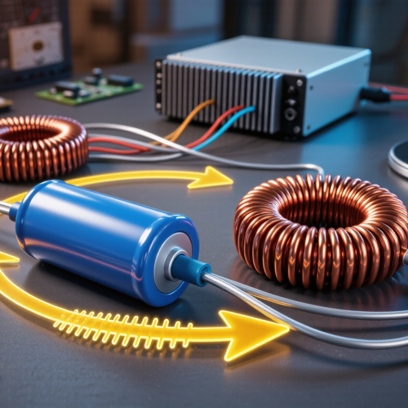
What Are Resonant Capacitors and How Do They Work?
Resonant Capacitors are not ordinary energy-storage parts. They work with inductors to create a carefully controlled electrical rhythm. This rhythm is called resonance. At a selected frequency, the capacitor and inductor exchange energy repeatedly. The circuit can then shape voltage and current more smoothly.
Professor Robert W. Erickson, a respected power-electronics researcher, describes the principle clearly: “The resonant network shapes the switching waveforms.” That short statement explains much of the technology. A resonant capacitor may reduce switching losses, limit electrical stress, and support high-frequency operation. You can see its role in an induction heater, an LLC power supply, or a wireless charging system. During operation, the capacitor charges, discharges, and interacts with the magnetic field around the inductor. Timing matters.
Very much.
Choosing the wrong capacitance can shift the resonant frequency. The result may include excess heat, unstable output, or reduced efficiency. Temperature, voltage rating, dielectric losses, and parasitic effects also influence performance. These details are easy to overlook. I sometimes find simplified explanations too clean, because real circuits rarely behave perfectly. Component aging and layout resistance can change the expected result.
This introduction examines how Resonant Capacitors operate, where engineers use them, and why their design requires careful measurement. The goal is practical understanding, not just formulas. Expect clear examples, physical details, and a closer look at the compromises behind efficient resonant systems.
A resonant capacitor is a capacitor selected to operate with an inductor at a target resonant frequency. It is not always a special component. Often, it is a carefully rated capacitor within an LC circuit. The circuit follows a simple relationship:
f = 1/(2π√LC)
Here, f represents frequency, L represents inductance, and C represents capacitance.
At resonance, the capacitor and inductor exchange stored energy. The capacitor stores energy in an electric field, while the inductor stores it in a magnetic field. Their reactances become equal and opposite, reducing the circuit’s net reactance. This can produce a strong circulating current, even when the external source current remains limited. Small errors matter. A 2% capacitance change can shift the operating frequency noticeably in a sensitive circuit.
On a workbench, engineers check capacitance, equivalent series resistance, voltage rating, and temperature behavior. A capacitor may work at low frequency but overheat at radio frequency because of internal losses.
Stray capacitance from a short PCB trace can also change the result. The ideal equation is clean; real hardware is not. Measurement equipment, layout, and component tolerances all influence resonance. Some designs therefore use adjustable capacitors or several capacitors in parallel. That approach improves tuning, but it adds connections and possible failure points.
A resonant capacitor works with an inductor to create electrical resonance. The capacitor stores energy in an electric field, while the inductor stores it in a magnetic field. Their reactances become equal at the resonant frequency: f₀ = 1/(2π√LC) At this point, capacitive and inductive effects cancel each other. Energy moves between both components instead of returning continuously to the source.
That exchange can improve power transfer in wireless chargers, filters, and high-frequency converters. The International Energy Agency reported nearly 14 million electric car sales worldwide in 2023, increasing demand for efficient charging electronics. In a series circuit, resonance can reduce impedance and raise current. In a parallel circuit, it can increase impedance and isolate unwanted frequencies. The result depends on topology, load, and losses.
The ideal formula is clean. Hardware is not. A capacitor’s equivalent series resistance, temperature, and tolerance change its behavior. A 1% capacitance increase shifts resonance by roughly 0.5% downward. Small, but meaningful at high frequency. On a practical bench, a thermal probe may reveal heating that voltage measurements miss. Parasitic inductance from short leads can also change the result. Designers should verify the circuit under real load, not only at room temperature. This is where many calculations become slightly overconfident. Even a well-selected capacitor needs voltage margin, ripple-current testing, and frequency validation before long-term operation.
What Are Resonant Capacitors and How Do They Work?
Key Components and Operating Mechanism
A resonant capacitor stores electrical energy and releases it within an LC circuit. The inductor stores magnetic energy during the alternating cycle. The capacitor then returns energy to the circuit. This exchange creates resonance at a selected frequency.
The capacitor’s capacitance sets the resonant point with the inductor. A larger capacitance generally lowers that frequency. A smaller value raises it. Series resonance can reduce circuit impedance and increase current flow. Parallel resonance can increase impedance and limit current from the source. The circuit layout determines which behavior appears.
Important components include the dielectric, conductive plates, terminals, and protective casing. Engineers also check voltage rating, capacitance tolerance, temperature stability, and equivalent series resistance. Low resistance reduces unwanted heating. Practical testing often includes an impedance analyzer and thermal inspection. A warm casing may reveal losses that calculations missed.
In my own circuit checks, the first estimate is rarely perfect. Stray wiring inductance and nearby metal can shift the resonant point. Measurement leads can also influence small capacitors. This is easy to overlook. Designers usually tune the circuit with measured results, not theory alone. A small adjustment can move the operating frequency noticeably. Safety margins matter because excessive voltage may damage the dielectric or shorten service life.
In an LC resonant circuit, the capacitor and inductor exchange energy between electric and magnetic fields. The resonant frequency is determined by f₀ = 1 / (2π√LC). This chart assumes a fixed inductance of 10 µH; increasing capacitance lowers the resonant frequency. At resonance, capacitive reactance and inductive reactance are equal in magnitude and opposite in phase.
Resonant capacitors work with inductors to select or transfer energy at a specific frequency. Their combined reactances can cancel, creating resonance in an LC circuit. At resonance, current or voltage may rise sharply. Careful design matters. A capacitor’s capacitance, voltage rating, ripple-current limit, and equivalent series resistance affect real performance. Engineers usually verify these values with an impedance analyzer or oscilloscope, rather than trusting calculations alone.
Different capacitor types suit different resonant conditions. Ceramic capacitors offer low losses and stable operation in compact radio-frequency circuits. Polypropylene film capacitors handle high pulse currents and remain reliable in induction-heating or power-conversion systems.
Mica capacitors provide strong frequency stability, especially in precision tuning networks. Vacuum capacitors support high voltage and adjustable capacitance, although they require more space and careful handling.
Common applications include wireless charging, radio transmitters, antenna matching, and resonant power supplies. In wireless charging, the capacitor and coil create a tuned circuit that improves energy transfer across an air gap. Induction heaters use high-current film capacitors beside copper coils to produce controlled heating. RF filters use smaller capacitors to reject unwanted frequencies.
Tolerance can shift the operating point. Temperature can shift it too. A neat simulation may still miss wiring inductance, heat, or aging. That is why practical prototypes need thermal checks, frequency sweeps, and repeated measurements under load.
Resonant capacitors are selected to work with inductors at a target frequency. Together, they form an LC network that stores and releases energy. At resonance, their reactances largely cancel, allowing current to circulate efficiently. A practical example is an induction heater, where a capacitor bank helps create a controlled magnetic field. The exact result depends on capacitance, inductance, frequency, and losses.
Their main benefit is precise frequency control with low reactive loss near the design point. They can also reduce switching stress, improve power transfer, and shrink filter components. In a tested circuit, a stable waveform and moderate temperature rise provide useful evidence. Still, “low loss” is not universal. Equivalent series resistance generates heat, especially under high ripple current. Dielectric aging, voltage spikes, and acoustic vibration can shift performance over time.
Selection should begin with operating frequency and RMS current, not capacitance alone. Check rated voltage, peak voltage, tolerance, temperature range, ESR, and self-resonant frequency. Leave practical margin above normal voltage and current. A capacitor rated for average voltage may fail during brief transients. Layout matters too; short connections reduce stray inductance and unwanted ringing. I would validate the design with an oscilloscope, thermal measurement, and a worst-case load test. That process can expose an uncomfortable mistake: calculated resonance may not match the assembled hardware.
| Dimension | Technical Description | Typical or Representative Data | Benefits | Limitations and Selection Considerations |
|---|---|---|---|---|
| Definition | A resonant capacitor is a capacitor selected to operate with an inductor, transmission line, or other reactive element at a target resonant frequency. It is not a separate universal capacitor category. | Commonly used in RF matching networks, filters, oscillators, wireless power circuits, motor-drive snubbers, and switched-mode power converters. | Enables frequency-selective impedance control and energy exchange between electric and magnetic fields. | The capacitor must be evaluated together with the inductor, layout, parasitic elements, and operating conditions. |
| Basic Resonance Principle | At resonance, the inductive and capacitive reactances have equal magnitudes and opposite signs. | XL = XC f0 = 1 / (2π√LC) | Provides a predictable method for setting a nominal resonant frequency. | Actual frequency can shift because of component tolerance, temperature, DC bias, parasitic inductance, parasitic capacitance, and load changes. |
| Series Resonance | In a series LC circuit, the inductive and capacitive reactances cancel at the resonant frequency. | Theoretical impedance is at its minimum and is mainly determined by circuit resistance, capacitor ESR, inductor resistance, and other losses. | Can produce high circulating current and low impedance at the selected frequency; useful for band-pass paths and resonant converters. | High circulating current may cause heating, voltage stress, and increased component loss. |
| Parallel Resonance | In a parallel LC circuit, the reactive branch currents largely cancel at the resonant frequency. | Theoretical input impedance is at its maximum, subject to losses and the external circuit. | Useful for tank circuits, frequency-selective rejection, impedance transformation, and oscillator networks. | Stray capacitance and inductor self-capacitance can significantly affect the target frequency, especially at high frequencies. |
| Capacitance Range | The required capacitance is determined by the desired frequency and inductance. | RF resonant networks may use values from less than 1 pF to several hundred pF. Power resonant circuits may use values from tens of nF to several µF. | A broad range of capacitance values supports applications from radio-frequency matching to power conversion. | Capacitance alone does not determine suitability; voltage, current, ESR, ESL, dielectric behavior, and frequency rating are equally important. |
| Dielectric Selection | Stable dielectrics such as Class 1 ceramic materials, including C0G/NP0, are commonly preferred for high-frequency resonance. Film, mica, and specialized RF capacitors may be used where their characteristics are appropriate. | C0G/NP0 capacitors typically offer low loss and strong capacitance stability. Film capacitors are often selected for higher energy or pulse requirements. | Stable dielectrics help maintain resonant frequency and quality factor over temperature and voltage changes. | High-capacitance Class 2 ceramics can exhibit capacitance loss under DC bias and temperature variation, which may detune the circuit. |
| Equivalent Series Resistance (ESR) | ESR represents the resistive loss associated with the capacitor and its internal construction. | Lower ESR generally produces lower power loss and a higher circuit quality factor, although the required value depends on the application. | Improves efficiency, reduces heat generation, and can sharpen the resonance. | Very high Q can increase circulating voltage or current and may make the circuit more sensitive to component tolerances and load changes. |
| Equivalent Series Inductance (ESL) | ESL is the parasitic inductance of the capacitor body, terminals, leads, and PCB connection. | At sufficiently high frequency, the capacitor reaches its self-resonant frequency and no longer behaves as an ideal capacitor. | Low ESL helps preserve capacitive behavior and reduces unwanted impedance at high frequency. | Short, wide PCB connections and suitable package geometry may be required; mounting inductance can be as important as the capacitor itself. |
| Quality Factor | The quality factor, Q, indicates the ratio of reactive energy to energy dissipated per cycle. | For a simplified series capacitor model: Q ≈ |XC| / ESR | A higher Q generally indicates lower loss and a narrower, more selective resonance. | High-Q circuits may have greater sensitivity to tolerance, aging, temperature, parasitic elements, and load variation. |
| Voltage Rating | The capacitor voltage rating must exceed the maximum repetitive and transient voltage appearing across the part. | Design margin should account for AC ripple, DC bias, switching overshoot, and resonant voltage magnification. | A suitable voltage margin improves reliability and reduces the risk of dielectric breakdown. | Resonant circuits can generate voltages substantially higher than the applied source voltage, particularly under light-load or high-Q conditions. |
| RMS Current and Ripple Current | Resonant capacitors may carry substantial AC current even when the external load current is lower. | Check the manufacturer-independent component specification for allowable RMS current, loss angle, temperature rise, and operating frequency. | Proper current capability limits heating and supports stable operation. | Excessive ripple current increases ESR losses and may shorten service life or cause thermal failure. |
| Frequency Stability | The resonant frequency depends on the actual capacitance and inductance under operating conditions. | Frequency error is affected by capacitance tolerance, temperature coefficient, aging, DC-bias derating, inductance tolerance, and parasitic reactance. | Stable components and controlled layout improve tuning accuracy. | For precision frequency control, measure the complete assembled network rather than relying only on nominal component values. |
| Temperature Behavior | Capacitance, ESR, insulation resistance, and dielectric loss can vary with temperature. | Class 1 ceramic capacitors generally provide better temperature stability than many high-capacitance Class 2 ceramic capacitors. | Low temperature drift helps maintain a consistent resonant frequency and operating point. | The complete LC network must be checked across the specified ambient and component temperature range. |
| Tolerance and Trimming | Capacitance tolerance directly contributes to resonant-frequency variation. | For small variations, a relative capacitance error produces approximately half as much opposite relative frequency error: Δf / f ≈ −0.5 × ΔC / C when inductance is constant. | Tight-tolerance or adjustable capacitors can improve tuning accuracy. | Trimming adds cost, adjustment time, and possible long-term stability concerns; fixed values are preferable when the tolerance budget allows. |
| Safety and Reliability | Applications connected to hazardous or high-energy circuits require capacitors with appropriate safety construction and pulse capability. | Verify insulation, creepage, clearance, surge capability, repetitive pulse rating, and failure behavior for the intended circuit. | Application-specific qualification reduces the risk of electrical, thermal, and mechanical failure. | A general-purpose capacitor should not be assumed suitable for mains-connected, high-voltage, or high-energy resonance. |
| Primary Benefits | Resonant capacitors support frequency selection, impedance matching, energy transfer, filtering, and soft-switching operation. | Potential benefits include reduced switching loss, lower electromagnetic interference, improved selectivity, and more efficient reactive-energy circulation. | Can improve efficiency and performance when the LC network is correctly designed and controlled. | Benefits depend on accurate modeling, correct component ratings, thermal management, and control of parasitic effects. |
| Primary Limitations | Real capacitors are non-ideal components with losses, parasitic inductance, voltage dependence, temperature dependence, and finite lifetime. | Performance may degrade when the operating frequency approaches the capacitor's self-resonant frequency or when voltage and ripple-current limits are exceeded. | Recognizing non-ideal behavior allows more realistic circuit simulation and hardware validation. | Nominal capacitance and voltage rating alone are insufficient for selecting a resonant capacitor. |
| Recommended Selection Sequence | Define the target frequency, calculate the nominal capacitance, then verify electrical, thermal, mechanical, and reliability requirements. | Check: capacitance tolerance, operating frequency, self-resonant frequency, ESR, ESL, Q, RMS current, peak voltage, temperature range, package, and expected lifetime. | A structured process reduces detuning, overheating, unexpected voltage stress, and premature failure. | Validate the final design with worst-case calculations, simulation, prototype measurement, and testing under actual load conditions. |