






A Cross Slide Table is a compact mechanical platform that moves a workpiece or tool along two perpendicular axes. One axis travels left and right. The other moves forward and backward. Together, these movements support controlled drilling, milling, routing, and inspection work.
Its design is straightforward but demanding. A rigid base supports two sliding plates, usually guided by dovetails, linear rails, or machined ways. Lead screws convert handwheel rotation into measured movement. A graduated collar may show small adjustments, while locking screws help prevent unwanted motion during cutting. On a workshop bench, a user might turn one handwheel by 0.5 millimeters, lock the axis, and make a cleaner hole without repositioning the entire machine.
The wider market explains why this accessory remains relevant. Grand View Research reported that the global machine tools market reached approximately USD 102.9 billion in 2023. The report also identified automation and precision manufacturing as continuing growth factors. In addition, the International Federation of Robotics recorded 541,302 industrial robot installations worldwide in 2023. These figures do not measure Cross Slide Table sales directly. That limitation matters.
Small tables still serve manual mills, drill presses, lathes, and educational machines. They can also support prototype work where a full CNC system would be excessive. However, accuracy depends on more than the product label. Backlash, table deflection, lubrication, clamping force, and operator technique all affect results. ISO 230-2 principles for machine-tool positioning accuracy offer useful guidance, although many low-cost tables are not tested to that standard. The practical lesson is simple: choose measurable rigidity and repeatability, not impressive packaging alone.
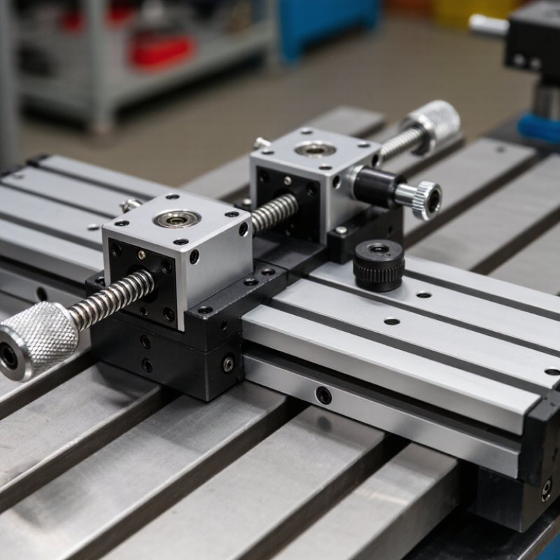
A cross slide table is a compact machine tool platform that provides two-axis positioning. Its X–Y travel lets a workpiece move horizontally and sideways across a fixed reference point. One axis usually moves left to right, while the second moves front to back. Handwheels, lead screws, and calibrated scales control these movements. Some tables use linear bearings, while others rely on fitted dovetail ways.
In practical machining, the table supports drilling, milling, slotting, and light inspection work. An operator secures the material with clamps or a small vise. Turning the X-axis handwheel shifts the part precisely along one direction. The Y-axis then adjusts its crosswise position. Locking screws help reduce movement during cutting. Small adjustments matter. Even a slight clamp shift can spoil a hole pattern.
Accuracy depends on construction, adjustment, and user technique. Backlash in the lead screw can create unwanted travel when the handwheel direction changes. I usually approach the final measurement from one direction and verify it with a dial indicator. That habit is useful, but not perfect. Dust, uneven clamping, and worn ways can still affect results. A clean surface and steady, repeatable hand pressure often matter more than impressive scale markings.

What Is a Cross Slide Table and How Does It Work?
A cross slide table supports and positions a workpiece with controlled movement along two perpendicular axes. Its core components determine accuracy, stability, and ease of adjustment. T-slots run across the table surface, allowing bolts, clamps, and fixtures to hold irregular parts securely. A clean slot matters. Chips under a clamp can slightly tilt the workpiece and affect the final cut.
Guideways support the moving sections and keep them aligned during travel. Depending on the design, they may use dovetail or linear arrangements. Lead screws convert handwheel rotation into measured table movement. Their threads provide mechanical advantage, but backlash can appear when direction changes. Handwheels usually include graduated scales, helping operators make small adjustments by feel and measurement. In practice, these markings are useful, but they should not replace a separate measuring tool.
Tips: Wipe the guideways before every setup. Apply suitable lubricant sparingly. Turn the handwheel gently, then lock the slide before cutting. Check for backlash by reversing direction and noting lost movement. Do not overtighten the slide lock. It may restrict motion or distort alignment. A quick test with a dial indicator can reveal errors that feel invisible by hand. The table may look rigid, yet poor clamping or uneven wear can still shift the workpiece. That detail is easy to overlook.
| Core Component | Primary Function | How It Works | Typical Design and Data Range | Common Materials | Key Performance Considerations | Routine Maintenance |
|---|---|---|---|---|---|---|
| T-Slots | Secure workpieces, fixtures, clamps, and accessories to the moving table. | T-shaped slots accept sliding nuts or T-bolts. Clamping hardware is positioned along the slot and tightened to hold the workpiece in place. | Slot width: 6–16 mm Typical slot spacing: 25–50 mm Common table sizes: 100–300 mm wide | Cast iron, steel, or aluminum alloy | Slot alignment, surface flatness, clamping access, and resistance to deformation affect setup accuracy. | Remove chips, clean the slot channels, and check T-bolts and nuts for damaged threads or burrs. |
| Guideways | Control the direction of table movement and support cutting or drilling loads. | Matched sliding surfaces or rolling elements constrain the table to a straight path while minimizing unwanted lateral and angular movement. | Common travel: 50–200 mm Typical clearance adjustment: 0.01–0.05 mm Typical forms: dovetail, box, or linear-roller guideways | Hardened steel, cast iron, or steel rollers | Rigidity, straightness, preload, wear resistance, and resistance to stick-slip motion determine positioning quality. | Keep surfaces clean, apply the specified way oil, and adjust gibs or preload only when excessive play is detected. |
| Lead Screw | Convert rotary input from the handwheel into controlled linear table movement. | The screw thread engages with a matching nut. As the screw rotates, the nut and attached table advance by one thread pitch per revolution. | Typical diameter: 10–20 mm Typical pitch: 1.5–3.0 mm Approximate travel per revolution: equal to the screw pitch | Hardened or alloy steel screw with bronze, brass, or polymer nut | Pitch accuracy, backlash, thread wear, lubrication, and screw straightness influence repeatability and positioning accuracy. | Clean exposed threads, lubricate with suitable way or screw lubricant, and periodically check axial play. |
| Handwheel | Provide manual control of table position and feed rate. | Turning the handwheel rotates the lead screw. The graduated dial indicates angular movement, which is converted into linear travel through the screw pitch. | Typical diameter: 60–120 mm Common dial graduations: 0.01–0.05 mm Typical full-turn travel: 1.5–3.0 mm | Aluminum, steel, cast iron, or engineering polymer | Handle comfort, dial readability, zero alignment, and backlash compensation affect manual positioning and repeatability. | Keep the dial and handle clean, verify the zero mark, and inspect the hub or keyway for looseness. |
| Base and Table Body | Provide structural support and connect the cross-slide assembly to a machine, drill stand, or workbench. | The base remains fixed while the table body travels along one or two perpendicular axes, depending on the design. | Typical working load: 50–300 kg Typical table thickness: 20–60 mm Common axis layouts: single-axis or X-Y | Cast iron, ductile iron, or machined steel | Mass, rigidity, mounting-hole alignment, surface flatness, and vibration resistance influence overall stability. | Check mounting bolts, remove chips from reference surfaces, and inspect for corrosion or impact damage. |
| Graduated Dial and Gib Adjustment | Support measurement and remove excessive clearance between the table and guideway. | The dial provides a visual indication of screw rotation, while the adjustable gib applies controlled pressure to improve guideway fit. | Dial increment: 0.01–0.05 mm Typical useful repeatability: 0.02–0.10 mm Adjustment type: tapered or parallel gib | Steel, cast iron, brass, or polymer bearing material | Dial zeroing, backlash, operator technique, and correct gib preload affect indicated and actual movement. | Adjust gradually, test movement across the full travel, and avoid overtightening, which can cause binding. |
A cross slide table converts rotary input into controlled X–Y linear travel. Its handwheels turn lead screws, while screw threads push or pull the table along precise axes. One screw moves the workpiece left and right. The other moves it forward and backward. Together, these movements position a drill, cutter, sensor, or small workpiece across a flat platform.
The motion depends on thread pitch, handle rotation, and mechanical clearance. For example, a screw with a 1 mm pitch advances the table 1 mm after one full revolution, ignoring small losses. Bearings reduce friction, while guideways keep travel straight. In practice, backlash can appear when the handle changes direction. The table may move slightly less than expected. I have found that tightening everything is not always better; excessive pressure can make movement stiff and inaccurate.
Tips: Turn the handwheel slowly and watch the scale, not only the workpiece. Approach the final position from the same direction when possible. Clean chips from the guideways before adjustment. Check zero alignment with a reliable rule or dial indicator. Remember that printed graduations may look precise, but they cannot reveal every error. Temperature, wear, and uneven clamping also affect results. A short test movement often exposes mistakes before they damage the setup.
A cross slide table supports controlled movement along two perpendicular axes. One axis moves the table forward and backward. The other shifts it sideways. Lead screws, guideways, handwheels, or motors create this motion. In machining, the table may carry a workpiece, fixture, or cutting tool.
Backlash is the clearance between mating screw and nut surfaces. When motion reverses, the handwheel may turn before the table moves. A visible 0.05 mm delay can affect hole spacing or edge finishing. Preloaded nuts can reduce backlash, but excessive preload increases friction and wear. Repeatability asks a different question: can the table return to the same position? It may reach a target accurately once, yet return with slight variation. Dust, temperature, lubrication, and clamping force can all influence results.
ISO 230-2 provides a structured method for evaluating positioning accuracy and repeatability. Measurements are taken at selected positions, often from both travel directions. A calibrated measuring system records commanded and actual locations. Reversal error becomes easier to identify when the approach direction changes. In practical checks, allow the table to reach a stable temperature and remove unnecessary load. My early inspections focused only on dial readings. That was incomplete. A smooth dial does not prove reliable positioning. Small errors can hide between graduations, especially near direction changes. Test records should include approach direction, target position, environmental conditions, and repeated readings. Consistent data is more useful than one impressive measurement.
What Is a Cross Slide Table and How Does It Work?
A cross slide table moves a workpiece or tool along two perpendicular axes. Its industrial specification starts with travel. Compact tables often provide 50–150 mm of movement, while heavy-duty units may exceed 300 mm. Load capacity depends on bearing design, mounting orientation, and overhang. A 100 kg rating may fall sharply when the load sits 150 mm from the slide center. That distinction matters.
Resolution describes the smallest displayed or commanded movement. A 0.01 mm readout shows hundredths of a millimeter, but it does not guarantee 0.01 mm positioning accuracy. Backlash, screw pitch error, guide wear, and thermal expansion still influence the result. ISO 230-2:2014 evaluates positioning accuracy and repeatability through multiple target positions and travel directions. ASME B5.54 also emphasizes machine-tool accuracy testing under controlled conditions. The number can mislead.
For real production work, compare travel with usable travel, not the headline figure. Check load capacity at the actual center of gravity. Resolution alone is insufficient. A table with 0.01 mm resolution may repeatedly stop within 0.03 mm, depending on preload and operator technique. That gap deserves attention. I would also request test conditions, measuring equipment, and repeatability data before specifying a table. Published figures are useful, but sometimes incomplete.
The chart shows representative non-branded specifications for cross slide tables in four size classes. Travel is the maximum linear movement along the slide, while load capacity is the recommended static load. Precision models commonly use 0.01 mm readouts, with positioning resolution typically specified at approximately 0.01–0.02 mm depending on the adjustment mechanism and measurement scale.

